
A drive changes motor speed by changing the frequency it supplies. Speed is proportional to frequency, but an induction motor runs a little below «synchronous speed», so a 4-pole motor at 60 Hz does not turn at 1800 rpm. Here is what to check when the calculation, the display and the bus value disagree.
Synchronous speed: 120 × f ÷ poles
ns (r/min) = 120 × f ÷ poles
  4 poles, 60 Hz → 1800 r/min
  4 poles, 50 Hz → 1500 r/min
  2 poles, 60 Hz → 3600 r/min   6 poles, 60 Hz → 1200 r/min
The 120 is «60 seconds × 2 (poles per pair)». Nameplates often omit the pole count, but the synchronous speed just above the rated speed gives it away: 1750 r/min at 60 Hz is 4 poles, 3500-something is 2 poles, 1160 is 6 poles.
Slip: why the real speed is lower
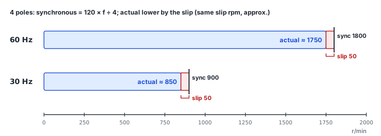
An induction motor's rotor must turn slower than the rotating field to produce torque. The difference is slip, and the nameplate rated speed (say 1750 r/min) is the speed at rated load. Slip = (1800 − 1750) ÷ 1800 ≈ 2.8 %; slip frequency = 60 − 1750 × 4 ÷ 120 ≈ 1.67 Hz. The YASKAWA A1000 manual uses exactly this formula (E2-02 = f − n × p ÷ 120) for its «motor rated slip» parameter and gives 0.5–3 Hz as a guideline for general-purpose motors.
Nameplate speed has a tolerance too: ABB's Motor guide gives, after IEC 60034-1, ±20 % on slip for 1 kW and above and ±30 % below 1 kW.
Speed at other frequencies
| Output frequency | Synchronous (4 poles) | Speed (rated slip 50 r/min kept, approx.) |
|---|---|---|
| 60 Hz | 1800 | 1750 |
| 45 Hz | 1350 | 1300 |
| 30 Hz | 900 | 850 |
| 15 Hz | 450 | 400 |
Below base frequency with constant V/f, the slip speed at a given torque can be taken as roughly unchanged, so slip grows as a percentage at low speed. Real slip varies with load, and with slip compensation or vector control the drive raises the frequency by the slip to track a speed command based on synchronous speed.
With a gearbox
A 10:1 reducer turns the output shaft at one tenth of motor speed. For 150 r/min at the output the motor needs 1500 r/min: on 4 poles that is 50 Hz synchronous plus the slip (50 r/min ≈ 1.67 Hz), about 51.7 Hz — or 50 Hz with slip compensation.
The rpm on the drive display comes from the pole setting
- On the LS S300, setting DRV-32 (Hz/rpm Select) to 1 (rpm Display) switches speed values to rpm. The manual notes the rpm values assume a 4-pole motor and change with the pole number setting (MOT1, 2-25); its formula 16 is Hz = rpm × poles ÷ 120.
- On the YASKAWA A1000, o1-03 = 2 shows r/min calculated from the maximum output frequency and the number of motor poles (E2-04).
- A wrong pole setting makes the rpm display wrong by a whole factor (a 4-pole motor set as 2 poles reads double). If the rpm looks odd, check the pole parameter first.
Reading output frequency over Modbus
| Device | Output frequency address | Unit |
|---|---|---|
| LS S300 | 0x0311 | 0.01 Hz |
| LS S100 | 0h000A | 0.01 Hz |
| YASKAWA A1000 | 0024H | set by o1-03 |
Addresses are as printed in the manuals, from PortDock's device register maps. To show the value in rpm, multiply by 120 and divide by the poles (synchronous speed); for the true speed, subtract the slip or use an encoder or speed monitor value. On drives like the YASKAWA where the display unit setting also applies to the bus value, check that setting too.
In PortDock
- «VFD Frequency ↔ Motor RPM» web tool: Hz and poles → synchronous speed, slip from the nameplate, gearbox output speed, and the Hz needed for a target rpm.
- «Motor Current Calculator» web tool: current and rated torque from output, voltage, efficiency and power factor.
- Modbus Master: load the drive register maps (LS S100, S300, G100, M100, H100, YASKAWA A1000, V1000) and read output frequency and current in a table.
Published 2026-10-23