
RS-485 Termination & Bias Resistor Calculator
Do failsafe bias resistors and 120/150 Ω termination keep the idle line above the 200 mV receiver threshold? Plus resistor power and cable length vs baud.
Why biasing is needed
RS-485 is half duplex, so while the master waits for a reply nobody drives the line. If the A–B voltage sits near 0 the receiver output is undefined, noise looks like a start bit and garbage bytes such as 00 or FF appear.
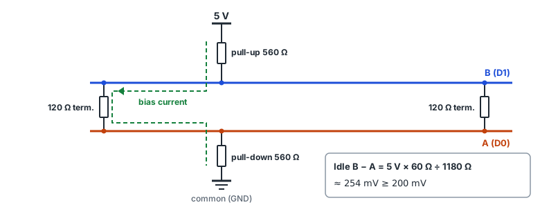
Biasing pulls B (D1) up to the supply and A (D0) down to common so B − A is positive at idle. That is the «1» (mark) state — the same as an idle UART — so it is not mistaken for a start bit.
Termination resistors sit across the pair and carry the bias current. The lower the termination (two 120 Ω = 60 Ω), the less idle voltage the same bias resistors produce.
Formulas
- Line resistance Rline = DC-coupled terminators in parallel (two 120 Ω → 60 Ω)
- Bias current I = Vcc ÷ (Rpull-up + Rline + Rpull-down)
- Idle differential voltage = I × Rline
- Largest equal R for 200 mV = (Vcc × Rline ÷ 0.2 − Rline) ÷ 2
- Rough length limit = min(1200 m, 10⁸ ÷ baud)
What the Modbus specification says (Modbus over serial line V1.02 §3.4)
- Termination: only near the two ends of the trunk, across A and B. A 150 Ω (0.5 W) resistor, or — when the line is biased — a 1 nF (10 V min) capacitor in series with 120 Ω (0.25 W) is better. Never on a derivation (stub).
- Biasing: if needed, at one place for the whole bus (usually the master). Pull-up to 5 V on D1, pull-down to common on D0, 450–650 Ω; 650 Ω allows more devices, and biasing reduces the maximum device count by 4.
- Devices: 32 are always allowed without a repeater.
- Length: up to 1000 m at 9600 bps with AWG26 or thicker. Stubs no longer than 20 m; with an n-way tap, 40 m ÷ n each.
Idle voltage for common combinations (both ends terminated, receiver loads excluded)
| Supply | Pull-up/down | Termination (both ends) | Idle voltage | Result |
|---|---|---|---|---|
| 5 V | 560 Ω | 150 Ω | 314 mV | ≥ 200 mV |
| 5 V | 650 Ω | 150 Ω | 273 mV | ≥ 200 mV |
| 5 V | 560 Ω | 120 Ω | 254 mV | ≥ 200 mV |
| 5 V | 680 Ω | 120 Ω | 211 mV | ≥ 200 mV |
| 5 V | 1000 Ω | 120 Ω | 146 mV | < 200 mV |
| 3.3 V | 560 Ω | 120 Ω | 168 mV | < 200 mV |
| 3.3 V | 390 Ω | 120 Ω | 236 mV | ≥ 200 mV |
Rough length limit by baud
| Baud | 10⁸ ÷ baud | Applied (max 1200 m) |
|---|---|---|
| 1200 | 83333 m | 1200 m |
| 2400 | 41667 m | 1200 m |
| 4800 | 20833 m | 1200 m |
| 9600 | 10417 m | 1200 m |
| 19200 | 5208 m | 1200 m |
| 38400 | 2604 m | 1200 m |
| 57600 | 1736 m | 1200 m |
| 115200 | 868 m | 868 m |
A rough value combining TI's rule of thumb «bps × m ≤ 10⁸» and the recommended maximum of about 1200 m. Real limits depend on cable gauge and capacitance, number of devices and noise; the Modbus specification states 1000 m at 9600 bps.
FAQ
120 Ω or 150 Ω termination?
Match the cable's characteristic impedance; common RS-485 twisted pair is about 120 Ω. The Modbus specification gives a 150 Ω resistor, or 1 nF in series with 120 Ω when the line is biased. Either way, only at the two ends of the line.
My converter has a bias switch — should I turn it on?
Turn biasing on at one place for the whole bus (usually the master side). If several devices each add bias, the resistors combine in parallel and load the drivers more. Check whether a device enables bias by default in its manual.
Is 560 Ω enough with a 3.3 V transceiver?
With two 120 Ω terminators (60 Ω): 3.3 × 60 ÷ (560 + 60 + 560) ≈ 168 mV, below 200 mV. Use smaller bias resistors (e.g. 390 Ω), 1 nF + 120 Ω termination to block the DC path, or a transceiver with built-in failsafe (offset receiver threshold).
For the full wiring checklist see RS-485 wiring checks: no reply or garbled data.