
RS-485 wiring has two kinds of resistors. «Termination» at the two ends of the line reduces reflections; «bias» resistors at one place on the bus (pull-up and pull-down, also called failsafe) define the line state when nobody transmits. Both sit on the same pair and affect each other, so calculate them together.
Termination: at the two ends only
A terminator goes across A and B and should match the cable's characteristic impedance. TI notes that within ±20 % of the characteristic impedance is fine and typical values run from about 90 to 120 Ω. The Modbus specification gives a 150 Ω (0.5 W) resistor, or — when the line is biased — a 1 nF (10 V min) capacitor in series with 120 Ω (0.25 W) as the better choice. Either way, only near the two ends of the trunk, never on a stub.
Terminating at every device puts them in parallel and loads the driver. The standard RS-485 driver output test requires at least 1.5 V differential into 54 Ω; three 120 Ω terminators make 40 Ω, a heavier load and a smaller signal.
Biasing: why it is needed
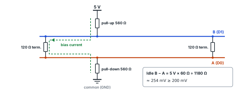
On half-duplex RS-485, nobody drives the line while the master waits for a reply. With termination only, the A–B voltage then sits near 0, the receiver output is undefined, noise looks like a start bit and garbage bytes such as 00 or FF appear. Biasing pulls B (D1 in Modbus terms) up to 5 V and A (D0) down to common so that B − A is positive at idle — a «1» (mark).
Calculating the bias value
Receivers produce a defined output for differential inputs of ±200 mV or more. The voltage the bias current develops across the parallel end terminators must exceed 200 mV.
Rline = terminators in parallel (two 120 Ω → 60 Ω)
Idle voltage = Vcc × Rline ÷ (Rpull-up + Rline + Rpull-down)
Example: 5 V × 60 ÷ (560 + 60 + 560) ≈ 254 mV
| Supply | Pull-up/down | Termination (both ends) | Idle voltage | 200 mV |
|---|---|---|---|---|
| 5 V | 560 Ω | 150 Ω | 314 mV | above |
| 5 V | 650 Ω | 150 Ω | 273 mV | above |
| 5 V | 560 Ω | 120 Ω | 254 mV | above |
| 5 V | 1 kΩ | 120 Ω | 146 mV | below |
| 3.3 V | 560 Ω | 120 Ω | 168 mV | below |
| 3.3 V | 390 Ω | 120 Ω | 236 mV | above |
The Modbus specification puts biasing, if needed, at one place for the whole bus (usually the master): pull-up to 5 V and pull-down to common, 450–650 Ω. 650 Ω allows more devices on the bus, and biasing reduces the maximum device count by 4. With 3.3 V transceivers the same resistors often fall short, so use smaller resistors, block the DC path with 1 nF + 120 Ω termination, or pick a transceiver with built-in failsafe (offset receiver threshold).
Bias enabled in several places
USB-RS485 converters, PLC communication cards and devices often have a bias switch or jumper. Enabling several puts the pull-ups and pull-downs in parallel, lowering the resistance and making every driver push that much more current. Enable one and disable the rest, and check device manuals for bias enabled at the factory.
Telling problems apart
| Symptom | Check first |
|---|---|
| Bytes such as 00 or FF arrive while no request is sent | No bias, or idle voltage below 200 mV |
| An extra byte in front of replies, CRC fails | Too little bias — the receiver catches noise as a driver switches on |
| Works on short/slow lines, fails when longer or faster | Missing termination, or not at the two ends |
| Signals weaken and fail as devices are added | Terminators on middle devices, bias enabled in several places |
| Everything set right, only far devices fail | Baud vs length (roughly bps × m ≤ 10⁸), common (GND) wire, A/B polarity |
In PortDock
- «RS-485 Termination & Bias Calculator» web tool: enter supply, pull-up, pull-down and termination type to get the idle voltage against 200 mV, resistor power, the largest bias resistors that still reach 200 mV, and a rough length limit per baud rate.
- Serial: leave reception on without sending and any garbage bytes between frames show up in HEX. Compare with bias on and off.
- Modbus Master counts CRC errors per table, so compare the counts over the same period before and after changing termination or bias.
Published 2026-10-23