
CAN Bit Timing Calculator
From CAN clock, bit rate and sample point, find the prescaler, time quanta, PROP_SEG, PHASE_SEG1/2 and SJW, with each one's oscillator tolerance.
Inside one bit
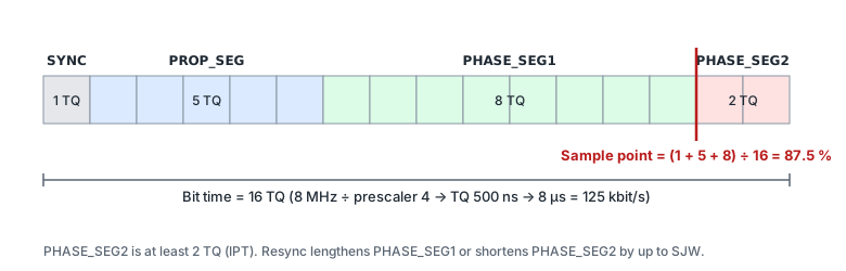
- TQ = prescaler (BRP) ÷ CAN clock
- Bit time = (1 + PROP_SEG + PHASE_SEG1 + PHASE_SEG2) × TQ, bit rate = 1 ÷ bit time
- Sample point = (1 + PROP_SEG + PHASE_SEG1) ÷ total TQ
- Oscillator tolerance Δf < SJW ÷ (20 × total TQ) and Δf < min(PS1, PS2) ÷ (2 × (13 × total TQ − PS2))
Segment rules
- SYNC_SEG is fixed at 1 TQ, PROP_SEG 1–8 TQ, PHASE_SEG1 1–8 TQ, and a bit is 8–25 TQ (AN1798 table 1).
- PHASE_SEG2 is at least the information processing time (IPT, 2 TQ). Microchip's documentation limits it to PHASE_SEG1; AN1798 table 1 gives MAX(IPT, PHASE_SEG1). This calculator checks «IPT ≤ PHASE_SEG2 ≤ MAX(IPT, PHASE_SEG1)».
- SJW (resynchronisation jump width) is at least 1 and at most 4 and PHASE_SEG1. This calculator uses min(4, PHASE_SEG1), as in AN1798 step 5.
- Registers usually take TSEG1 (= PROP_SEG + PHASE_SEG1), TSEG2 (= PHASE_SEG2), BRP and SJW; whether you write «value − 1» depends on the chip. Follow its bit timing register description.
What the oscillator tolerance means
- Every node's clock is slightly different, so SJW and the phase segments must absorb the phase error that builds up between resynchronisations. AN1798 equation (10) covers the 10 bits guaranteed by bit stuffing; equation (11) the 13 bits after an error flag.
- The smaller of the two is the clock error (±) the combination tolerates. In AN1798 example 2 (8 MHz, 125 kbit/s) 16 TQ with PS1 = PS2 = 6 allows 1.25 %, while 8 TQ with PS1 = PS2 = 3 allows 1.485 % — fewer quanta, more margin.
- A later sample point (shorter PHASE_SEG2) helps with propagation delay on long buses but lowers the equation (11) tolerance.
PROP_SEG and bus length
PROP_SEG must cover the round-trip delay between nodes at opposite ends: t = 2 × (cable delay + transmitter delay + receiver delay), PROP_SEG ≥ roundup(t ÷ TQ). AN1798's example uses 5 ns/m cable and 150 ns transceiver delay — take real values from your cable and transceiver datasheets. Leave the fields empty and PROP_SEG only needs to be at least 1 TQ.
FAQ
How do I get an 87.5 % sample point?
With 16 TQ and PHASE_SEG2 = 2 TQ: (16 − 2) ÷ 16 = 87.5 %. With 8 TQ you would need PHASE_SEG2 = 1 TQ, which the IPT (2 TQ) rule forbids, so the most is 75 %.
Why are there no results?
The clock does not divide into the bit rate as prescaler × TQ count. Allow a small rate error, change the CAN clock, or raise the maximum prescaler to what your chip supports.
Are more time quanta better?
They allow finer sample point steps, but do not always increase the oscillator tolerance. Compare the «Osc. tolerance» column with your oscillator's real accuracy (crystal, internal RC…).
Does it handle the CAN FD data phase?
No — it uses classic CAN (CAN 2.0) rules. The CAN FD data phase has other ranges and transmitter delay compensation; follow the chip manual.