
4–20 mA Loop Load Calculator
Can a 2-wire 4–20 mA loop supply drive the 250 Ω input, cable and indicators? Voltage left at the transmitter, maximum load resistance and cable length.
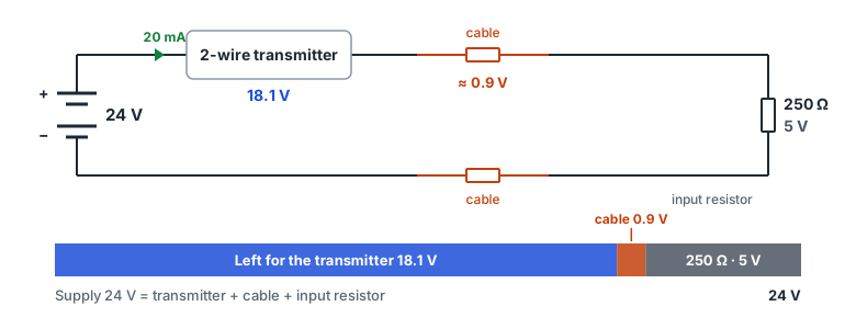
Formulas
- Cable loop resistance = 2 × ρ × one-way length ÷ cross-section (copper ρ20 = 1/58 Ω·mm²/m)
- Loop resistance = input resistor + cable + other resistance
- Transmitter voltage = supply − max current × loop resistance − other voltage drop
- Maximum load = (supply − transmitter minimum − other voltage drop) ÷ max current
Example: with a 24 V supply, a 12 V transmitter minimum and 20 mA, the maximum load is (24 − 12) ÷ 0.02 = 600 Ω. After a 250 Ω input resistor, 350 Ω is left for cable and indicators.
Why check at maximum current
The voltage lost in the loop resistance grows with current, so the transmitter has the least voltage at the highest current — hence the check at 20 mA. If the transmitter is set to signal failures at 21 mA or more (NAMUR NE 43), the loop must carry that current too for the failure signal to arrive, so try that value. Also check which current the load diagram in the transmitter manual assumes.
Symptoms of too little voltage
- Readings are right at the low end but stop rising near the top (stuck at, say, 18 mA).
- The top of the range disappeared after lengthening the cable or adding an indicator or isolator.
- Values are clipped only when the supply sags (when other loads switch on).
FAQ
Why does a 250 Ω resistor give 1–5 V?
Ohm's law: 4 mA × 250 Ω = 1 V and 20 mA × 250 Ω = 5 V. It is how a voltage-only input reads a 4–20 mA signal.
How far can I run a loop on 24 V?
It depends on the transmitter minimum voltage and input resistor. With 12 V minimum, 250 Ω and 20 mA the cable may use up to 350 Ω; with 0.75 mm² copper (about 0.046 Ω/m out and back) that is about 7.6 km one way, so indicators and barriers usually run out first.
Does this apply to 4-wire transmitters?
A 4-wire (active output) transmitter has its own supply and drives the current. Compare the total loop resistance with the «maximum load» in its output specification instead of a supply voltage.
To convert the current to engineering units or PLC counts, use the 4–20 mA Scaling Calculator.