
4–20 mA is how pressure, flow and temperature transmitters send a measurement as current. Current is the same everywhere in a series loop, so long wires and their resistance do not change the reading as long as the supply voltage is sufficient. The low end, 4 mA, is 0 %; the high end, 20 mA, is 100 %.
Live zero: why 4 mA
Because 4 mA flows even at 0 %, «measurement is zero» and «no current» (open loop, power off) can be told apart. A 0–20 mA signal puts 0 % at 0 mA and cannot. And since current always flows, a 2-wire transmitter can draw its own operating power from the same two wires that carry the signal.
Scaling formula
value = low + (current − 4) ÷ 16 × (high − low)
| Current | % | 0–10 bar transmitter | Voltage across 250 Ω |
|---|---|---|---|
| 4 mA | 0 | 0 bar | 1 V |
| 8 mA | 25 | 2.5 bar | 2 V |
| 12 mA | 50 | 5 bar | 3 V |
| 16 mA | 75 | 7.5 bar | 4 V |
| 20 mA | 100 | 10 bar | 5 V |
A device with voltage inputs only can take 4–20 mA as 1–5 V across a 250 Ω resistor (Ohm's law). PLC analog inputs convert the current to integer counts — the SIMATIC S7-1500 maps low–high to 0–27648 and the MELSEC iQ-R to 0–32000 (per the manufacturers' manuals). If counts look wrong, convert them back to mA first.
2-wire, 3-wire and 4-wire
| Type | Wiring | Power |
|---|---|---|
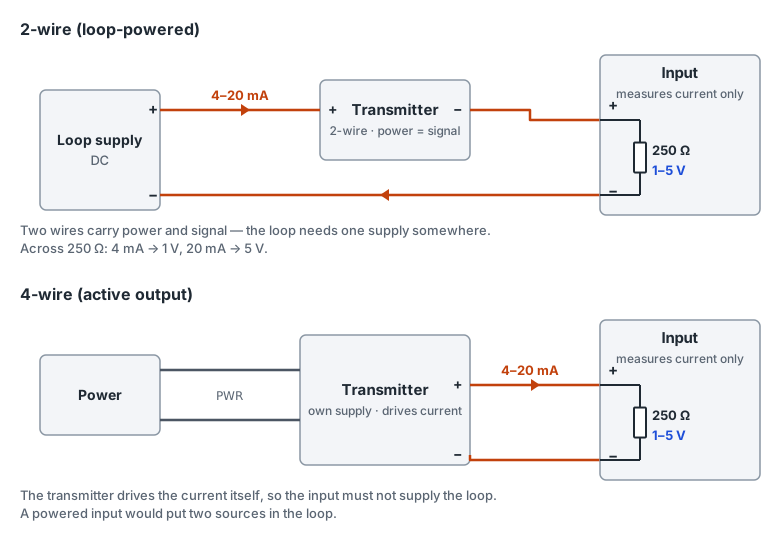
| 2-wire (loop-powered) | Two wires carry both power and signal | A DC supply somewhere in the loop runs the transmitter |
| 3-wire | Supply +, common, signal output | Supply and signal share the common wire |
| 4-wire (active output) | Two power wires + two signal wires | Separately powered; the transmitter drives the current itself |
The first wiring question is «who powers the loop?». A 2-wire transmitter cannot drive current on its own, so the loop needs a supply somewhere. Check in the manual whether the receiving input supplies power or only measures current. A 2-wire transmitter on an unpowered input leaves the loop with no supply at all; a 4-wire (active) transmitter on a powered input puts two sources in the loop.
When the loop voltage is too low
In a 2-wire loop the supply must exceed «the transmitter's minimum operating voltage + 20 mA × loop resistance (input resistance + wire resistance + any indicators)». If it does not, the current stops rising near the top of the range. For example, 20 mA through a 250 Ω input drops 5 V across that resistor alone. The transmitter's minimum voltage is in its manual.
Failure signals: NAMUR NE 43
Transmitters following NAMUR recommendation NE 43 output measurements only within 3.8–20.5 mA and signal a detected failure with 3.6 mA or less, or 21 mA or more. Whether a failure drives the output low or high is set in the transmitter; its manual explains how.
| Current received | Meaning | Check first |
|---|---|---|
| Near 0 mA | No current flows | Open loop, loop supply off or fuse, reversed polarity on a 2-wire device |
| ≤ 3.6 mA | NE 43 failure signal (low) | Transmitter diagnostics, broken sensor |
| 3.6–3.8 mA | Outside the NE 43 measurement range | Process below the low end, zero |
| 3.8–4 mA | Below the low end, inside the measurement range | Zero adjustment |
| 20–20.5 mA | Above the high end, inside the measurement range | Range setting |
| 20.5–21 mA | Outside the NE 43 measurement range | Process above the high end |
| ≥ 21 mA | NE 43 failure signal (high) | Transmitter diagnostics, short between signal wires |
Finding an open loop on site
- 1. Look at mA, not the engineering value. PLC counts and engineering values pass through scaling, so a wrong scaling setup makes them look odd. Convert the count back to mA with a scaling calculator.
- 2. Put a multimeter on its current range in series with the loop and measure the actual current. If the supply terminals have voltage but the current is zero, the loop is broken somewhere.
- 3. At 3.6 mA or below, or 21 mA or above, the transmitter may be reporting its own failure. Check its display or diagnostics menu.
- 4. A reading off by a constant ratio points to the scaling ranges (engineering low/high, count range); a constant offset points to the zero.
- 5. If the value fluctuates, check the shield grounding and whether the signal cable shares a duct with drive output cables.
In PortDock
- «4–20 mA Scaling Calculator» web tool converts between current, engineering units, % and PLC counts and flags 4–20 mA values in the NE 43 failure range or outside the measurement range. Count ranges for S7-1500, MELSEC iQ-R and Compact I/O are built in.
- For converters and meters that publish analog values over Modbus, read the registers with Modbus Master and watch fluctuations on its trend lines.
- Devices that print values over serial can be graphed live with Plot and saved as CSV.
Published 2026-10-22