
Power meters and plant data show numbers like «power factor 0.85». Power factor tells you how much extra current flows for the same work. Here is what it is, how capacitors raise it and how to size them.
kW, kvar, kVA and power factor
- Real power P (kW): power that becomes work, such as heat or rotation.
- Reactive power Q (kvar): power that magnetizes a motor and flows back and forth without doing work.
- Apparent power S (kVA): their combined size; for three-phase, √3 × line voltage × current. S = √(P² + Q²).
- Power factor cos φ = P ÷ S. ABB's Motor guide calls the ratio of real power (kW) to apparent power (kVA) the power factor, with P and Q together making up S.
Cables, breakers and transformers are sized by current, so the same kW at a lower power factor needs bigger equipment. 100 kW at 400 V three-phase is 144 A at power factor 1, 180 A at 0.8 and 192 A at 0.75.
Motor power factor
According to ABB's Motor guide (§4.10), motor power factor is usually between 0.7 and 0.9, lower for small motors and higher for large ones. It also falls with load: in the same guide's table a motor rated at 0.85 has 0.81 at 3/4 load, 0.72 at 1/2 and 0.54 at 1/4. Installations with many motors therefore have a lower overall power factor, and ABB notes that power suppliers sometimes require it to be raised.
Raising the power factor with capacitors
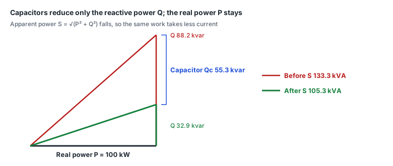
A capacitor supplies reactive power opposite to a motor's, so connecting it in parallel reduces the reactive power drawn from the supply. ABB's Motor guide likewise describes raising the power factor by «connecting capacitors to the supply which absorb reactive power». Real power stays the same; only apparent power and current fall.
Qc (kvar) = P (kW) × (tan φ1 − tan φ2)
tan φ = √(1 − cos²φ) ÷ cos φ

100 kW, 0.75 → 0.95:  tan φ1 = 0.882, tan φ2 = 0.329
Qc = 100 × 0.553 = 55.3 kvar
Line current (three-phase 400 V): 192.5 A → 151.9 A
ABB Motor guide Table 4.7 tabulates tan φ1 − tan φ2 as a «constant K» (uncompensated 0.50–0.90 → compensated 0.80, 0.85, 0.90, 0.95). For a motor it uses Q = K × P ÷ η: the shaft output P divided by efficiency η gives the input power, multiplied by K.
kvar to µF
One capacitor: C = Q × 1000 ÷ (2π × f × U²)   [F]   (Q its kvar, U the voltage across it)

Three-phase delta: 3 capacitors, Qc ÷ 3 each, U = line voltage
Three-phase star:  3 capacitors, Qc ÷ 3 each, U = line voltage ÷ √3  → 3× the capacitance

55.3 kvar, 400 V, 50 Hz, delta: 18.4 kvar → about 367 µF × 3
ABB's Motor guide gives C = 3.2 × 10⁶ × Q ÷ U² at 50 Hz. 3.2 × 10⁶ is 10⁹ ÷ (2π × 50) ≈ 3.18 × 10⁶ rounded; with Q in kvar and U in volts the result is in µF. The same capacitor gives 1.2 times the kvar at 60 Hz as at 50 Hz, so match the frequency.
Cautions at the motor (ABB Motor guide §4.10)
- Over-compensation can make an induction motor self-excite and run as a generator, so it is normal practice not to compensate for more than the motor's no-load current.
- Capacitors connected in parallel with single phases of the winding can make star-delta starting difficult or impossible.
- On a two-speed motor with separate windings, capacitors should not remain in circuit on the unused winding.
Lagging, leading and the target
With current behind voltage, as in a motor, the power factor is lagging; with too much capacitance the current leads. The closer the target is to 1.0, the faster the kvar grows and the easier it is to go leading when the load drops. Plants with varying load often use automatic correction that switches several steps. Utility requirements and tariffs differ by contract, so check your supply agreement (we have not checked the original terms, so no figures here).
Reading power factor from a meter
- Digital power meters give power factor, reactive and apparent power as Modbus registers. The LS ELECTRIC GIMAC1000 sends power factor as a 32-bit float (f32) with negative meaning leading, and the Rootech Accura 2300 gives per-phase and total power factor as f32 (PortDock device maps).
- A 32-bit float spans two registers, so the word order must match. If values look wrong, see the float word order guide.
- A negative power factor is not a fault — each manual states how its device signs leading values.
In PortDock
- «Power Factor Correction Capacitor Calculator» web tool: kW, present and target power factor → kvar needed, µF per capacitor in delta or star, current before and after; also the power factor after a given kvar and over-compensation.
- «Three-Phase Power Calculator» web tool: from voltage, one of amps, kW or kVA, and power factor, get the rest; power factor from kW and kVA. For current from motor output, use the «Motor Current Calculator».
- Modbus Master: poll power factor and reactive power from a power meter device profile and watch how they change with load in the trend view.
Published 2026-10-23