
Power meters and ammeters do not take hundreds of amps directly; they measure a small secondary current through a current transformer (CT). Installing a meter or reading current over Modbus brings up «CT ratio settings» and «CT burden». The arithmetic is simple, but wiring distance changes the result a lot.
What a CT does
ABB's instrument transformer guide (1VAP420003-TG) describes a CT as connected in series with the line to transform the line current to the standard 5 A suitable for meters and relays (p.5), and gives typical CT outputs of 1–5 A (p.4). The secondary circuit is grounded to keep the voltage at the meters safe (p.5).
CT ratio and secondary current
CT ratio = rated primary ÷ rated secondary
200/5 → 40

Secondary = primary ÷ 40
150 A primary → 3.75 A secondary
200 A primary → 5 A secondary
4 A measured at the meter → 160 A primary
Some CTs have several taps. ABB's example (p.6) is a 600:5 multi-ratio CT where the pair of secondary terminals (X1-X2, X2-X3 …) selects 50:5 to 600:5. The terminals you wired are the ratio, so check the nameplate connection table.
Setting the CT ratio on a power meter
- Enter the CT's rated primary and secondary (e.g. 200 and 5) and the meter multiplies the secondary current by the ratio to show real current and power. If the setting does not match the CT, current, power and energy are all off by that ratio.
- The LS ELECTRIC GIMAC1000 device map notes that all measurements are Float32 in engineering units with the PT/CT ratio applied, and the Rootech Accura 2300 map says no separate PT/CT scaling is needed (PortDock device maps, from each manual). Do not multiply Modbus values by the CT ratio again.
- Check what percentage of the CT's rated primary your normal load is. A 20 A load on a 200/5 CT gives 0.5 A secondary (10 %), at the bottom of the meter's range.
Burden — the circuit the CT drives
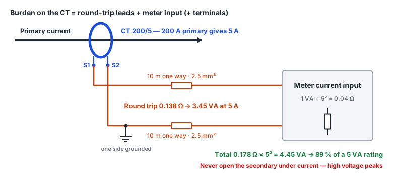
The burden is the whole impedance connected to the CT secondary (ABB p.13). A CT's ratio and phase errors depend on it, so keep within the rated burden (VA) on the nameplate. Looking at the resistive part only, it is Ohm's law.
Burden VA = (rated secondary current)² × (round-trip leads + meter input + terminals)
Meter input Ω = meter burden VA ÷ (rated secondary current)²
Round-trip leads = (2 × one-way length) ÷ (58 × area)   (copper at 20 °C, Ω)

200/5, 10 m one way, 2.5 mm², meter 1 VA:
  leads 0.138 Ω → 3.45 VA,  meter 0.04 Ω → 1 VA
  total 0.178 Ω → 4.45 VA  (89 % of 5 VA)
Same, 30 m one way:  11.34 VA  (227 % — over the rating)
Take the meter's VA from its datasheet («current input burden»). The calculation adds resistance only; if the meter input has reactance, the real impedance differs slightly.
1 A and 5 A secondaries
| Leads (copper 2.5 mm²) one way | Round-trip Ω | Lead burden, 5 A secondary | Lead burden, 1 A secondary |
|---|---|---|---|
| 10 m | 0.138 | 3.45 VA | 0.138 VA |
| 30 m | 0.414 | 10.34 VA | 0.414 VA |
| 50 m | 0.690 | 17.24 VA | 0.690 VA |
On the same wire, lead burden (I²R) with a 1 A secondary is 1/25 of 5 A. At 30 m one way a 5 A CT passes 10 VA on the leads alone, while a 1 A CT with a 1 VA meter is about 1.41 VA in total. For long runs, use thicker wire, move the meter closer, or use a 1 A secondary CT with a 1 A meter input. Check which secondary current your meter takes first.
Standard burdens (IEEE C57.13)
ABB's guide (p.13) lists the IEEE C57.13 metering burdens for 5 A secondaries: B-0.1 (0.1 Ω, 2.5 VA), B-0.2 (0.2 Ω, 5.0 VA), B-0.5 (0.5 Ω, 12.5 VA), B-0.9 (0.9 Ω, 22.5 VA) and B-1.8 (1.8 Ω, 45 VA), at power factor 0.9 and 60 Hz. For a CT not rated 5 A, multiply the ohms by (5 ÷ rated current)²; the VA at rated current stays the same — 2.5 VA on a 1 A CT is 2.5 Ω. IEC rated-burden notation and accuracy-class error limits are not covered here: we have not checked the IEC 61869-2 text.
Ratio error and accuracy classes
The nameplate ratio is the «marked ratio»; the actual ratio is slightly higher or lower. ABB's guide (p.10) defines the difference as the ratio correction factor RCF = actual ratio ÷ marked ratio. An actual 20.2 : 1 against a marked 20 : 1 is RCF 1.01, a 1 % ratio error; with RCF above 1 the meter reads low, so multiply readings by the RCF.
According to the same guide (p.12), IEEE C57.13 has metering classes 0.3, 0.6 and 1.2 for CTs, the 0.6 and 1.2 classes allowing twice and four times the error of 0.3. Twice the error is permitted at 10 % of rated current as at 100 %, and the limits apply at the specified burden and also at zero burden. A class holds under its burden conditions; if the actual burden exceeds the rating, do not expect the class.
Never open the secondary
ABB's guide (p.26): if a CT secondary is opened while current flows, all the primary current flows through the exciting branch and a high voltage appears at the secondary terminals. The RMS value is limited by core saturation and may not look dangerous on a voltmeter, but each current zero produces very high voltage peaks that can break down insulation and are dangerous to people. The guide says an open secondary should be considered a serious accident and, where larger CTs may be opened, a protective circuit should be permanently connected to the secondary terminals.
In PortDock
- «CT Ratio & Burden Calculator» web tool: primary ↔ secondary current by ratio, percentage of rated primary, round-trip leads + meter VA → total burden against the rating, and RCF from measured currents.
- «Three-Phase Power Calculator» web tool: check kVA, kW and kvar from the voltage, current and power factor the meter reports. For wire resistance by size, use the «Voltage Drop & Wire Size Calculator».
- Modbus Master: poll per-phase current from a power meter device profile (GIMAC1000, Accura and others) to see whether the CT ratio setting gives plausible load currents.
Published 2026-10-23