
Pressure transmitters, temperature converters and similar sensors output their value as 4–20 mA or 0–10 V. An MCU ADC, a PLC analog input module or a panel meter turns that into a number, and «scaling» turns the number back into bar or °C. The steps are always the same: signal → ADC input voltage → ADC code → engineering value. Every step is linear, so two end points are all you need.
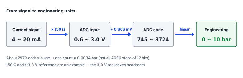
1. Signal to ADC input voltage
A current signal becomes a voltage across one shunt resistor (V = I × R). A voltage signal such as 0–10 V is reduced with a divider when it exceeds the ADC reference. Either way, the point is to put the top of the signal a little below the reference.
| Shunt | 4 mA | 20 mA | Reference | Result |
|---|---|---|---|---|
| 150 Ω | 0.6 V | 3.0 V | 3.3 V | About 9 % headroom — the top code (4095) is about 22 mA |
| 165 Ω | 0.66 V | 3.3 V | 3.3 V | 20 mA is exactly full scale — anything above clips |
| 250 Ω | 1 V | 5 V | 5 V | 20 mA is exactly full scale — anything above clips |
Without headroom, a reading just above 20 mA sticks at the top code and you cannot tell «exactly full» from «over range». For 0–10 V into a 3.3 V ADC, leave the same room with a ratio of 0.3 (10 V → 3.0 V). Pick standard divider resistors with the voltage divider calculator.
2. Voltage to code
1 LSB = V_REF ÷ 2^N                     (Microchip AN693)
code  = ⌊V_IN × 2^N ÷ V_REF⌋, max 2^N − 1     (ATmega328P §23.7, N bits)

12 bits, 3.3 V → 1 LSB = 0.806 mV
0.6 V → 744.7,  3.0 V → 3723.6      ← about 2979 codes in use
A 12-bit ADC does not use all 4096 steps here. Without the range below 4 mA (0–0.6 V) and above 20 mA (3.0–3.3 V) about 2979 codes remain, so for 0–10 bar one count is about 0.0034 bar — the real resolution of this circuit. Microchip's AN693 notes that even an ideal converter has up to ±½ LSB of quantization error, and real converters add offset and gain errors and non-linearity (DNL, INL): 1 LSB is the step you can resolve, not the accuracy.
3. Code to engineering value — a two-point line
value = low + (code − code_low) ÷ (code_high − code_low) × (high − low)

code 2234 → 0 + (2234 − 744.7) ÷ (3723.6 − 744.7) × 10 = 5.00 bar   (12 mA)
| Code | Signal | Value (0–10 bar) |
|---|---|---|
| 0 | 0 mA | −2.50 bar (open loop or no power) |
| 745 | 4.00 mA | 0.00 bar |
| 1489 | 8.00 mA | 2.50 bar |
| 2234 | 12.00 mA | 5.00 bar |
| 2979 | 16.00 mA | 7.50 bar |
| 3724 | 20.00 mA | 10.00 bar |
| 4095 | 22.0 mA | 11.25 bar (top code) |
- Keep code_low and code_high as decimals (744.7, 3723.6); rounding them shifts the end values slightly.
- On an integer-only MCU, compute in integer units such as 0.01 bar and multiply before dividing. Integer division drops the fraction, so dividing first tends to give 0.
- Shunt and reference tolerances and the ADC's offset and gain errors are all corrected when code_low and code_high come from two known points. AN693 also notes that gain error is easily compensated digitally.
4. Out of range and open loop
4–20 mA starts at 4 mA, not 0, so a reading far below the low end (near code 0 above) is not «0 bar» but an open loop or a transmitter supply problem. Showing values above the top as «out of range» separately is also good practice. Where faults begin (NAMUR NE 43 limits and so on) is summarized in the 4–20 mA scaling calculator.
5. Noise and the input filter
The ATmega328P datasheet (§23.6.1) says its ADC is optimized for sources of about 10 kΩ output impedance or less, and advises removing components above the Nyquist frequency (f_ADC/2) with a low-pass filter. An RC filter on the shunt voltage delays the response by τ = R × C, so choose it with the RC time constant calculator against the response you need. Averaging several readings in software is also common.
Values the device has already scaled
- PLC analog input modules output a fixed integer range instead of bits and reference: SIMATIC S7-1500 maps low–high to 0–27648 and MELSEC iQ-R to 0–32000 (per the makers' manuals). Use the same two-point line with that range.
- Modbus devices often send integers without a decimal point and define the scale or decimal position separately. The Autonics MT4W panel meter, for example, sends its reading as an integer with the decimal position in another input register (PortDock device map).
- PortDock Modbus Master shows raw values. Picking a device profile puts the scale in the register name, such as «(×0.01 Hz)», so multiply by it when reading.
In PortDock
- «ADC Resolution & Scaling Calculator» web tool: enter bits, reference, shunt (or divider ratio) and engineering range to see the value per count, code ↔ value and clipping.
- «4–20 mA Scaling Calculator» for PLC counts (0–27648…) and NE 43 limits; the voltage divider and RC time constant calculators for choosing input parts.
- Plot has no per-channel scale, so have the MCU send the scaled value as «press:5.00» and it plots in bar directly. If it sends raw codes, they are plotted as codes — check them with the calculator.
- Modbus Master: fill panel meter and temperature indicator registers from a device profile and apply the scale or decimal position to the raw values.
Published 2026-10-23